

Blogs

What Is an Automatic Zipper Machine and How Does It Work?

An automatic zipper machine is more than a fast sewing device. It is a coordinated production system that feeds, aligns, stitches, trims, and checks zipper components with limited manual handling. Understanding its operation helps manufacturers evaluate speed, consistency, maintenance needs, and product quality.

Tadao Yoshida, founder of YKK, expressed a principle that remains relevant to zipper manufacturing: “No one prospers without rendering benefit to others.” Although he was not describing one specific automatic zipper machine, the idea reflects responsible engineering. A reliable machine should benefit operators, manufacturers, and end users through safer operation and consistent results.

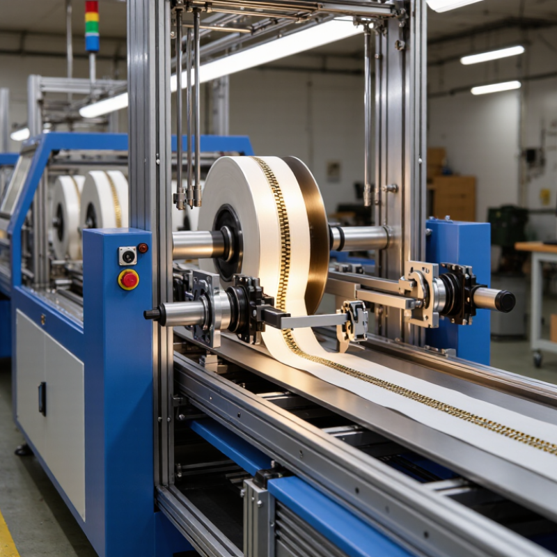
Inside the equipment, guide rollers position the zipper tape. Sensors detect alignment. Stitching units secure the chain to fabric. Cutting tools then separate finished sections. Some advanced models include tension control, automatic lubrication, and defect detection. The process can look almost effortless. It is not.

A small variation in tape tension may create crooked teeth. Dust can affect sensors. Poor calibration may produce repeated defects within minutes. These details matter. They also show why machine performance cannot be judged by speed alone.

This article will explain how an automatic zipper machine works, which components control its movement, and where quality problems commonly begin. It will also examine practical factors such as setup time, operator skill, energy use, and routine maintenance. No machine is perfect. Even highly automated equipment needs thoughtful supervision, accurate settings, and regular inspection.
What Is an Automatic Zipper Machine and How Does It Work?

Automatic Zipper Machines: Definition, Types, and Industrial Applications

An automatic zipper machine feeds, positions, joins, and cuts zipper components with limited manual handling. Sensors guide the tape, teeth, sliders, and fabric panels through synchronized stations. A programmable controller adjusts speed, tension, heating, and cutting length. Operators mainly load materials, inspect samples, and correct alignment.

Common types include automatic zipper closing machines, slider attaching machines, cutting machines, and integrated production lines. Coil zipper systems require different feeding controls from metal or molded-tooth systems. In a factory, a closing unit may resemble a compact metal tunnel. The tape enters continuously, while rollers maintain pressure and the needle or sealing head completes the joint. Small errors matter. A slight offset can cause rejected garments or difficult slider movement.

Industrial applications cover apparel, luggage, footwear, home textiles, protective workwear, and automotive interiors. Grand View Research’s zipper market analysis projects continued market growth, supported by rising garment and travel-goods production. The International Federation of Robotics reported 541,302 new industrial robots installed worldwide in 2023. That figure does not measure zipper equipment directly, but it shows the broader shift toward automated manufacturing. Machine selection should consider zipper material, product width, hourly output, changeover time, and maintenance access. Reported capacity figures can be optimistic; real output falls when materials vary or operators need frequent adjustments. Reliable trials remain essential before full-scale installation.

Key Components: Feeders, Molds, Sensors, Servos, and Control Systems

What Is an Automatic Zipper Machine and How Does It Work?

An automatic zipper machine joins zipper tape, teeth, sliders, and finished lengths with controlled timing. Its feeders guide coils or pre-cut parts into the working zone. Small guide rollers keep the tape flat. A mold then holds the zipper in a fixed position during forming, cutting, or slider insertion. This matters because a few millimeters of movement can create uneven teeth.

Sensors check tape presence, tooth alignment, length, and slider position. Optical sensors can detect gaps, while pressure sensors identify feeding resistance. Servos control the feeder, cutter, and insertion tools with precise speed changes. The control system connects these signals through a programmable interface. Operators can adjust stroke distance, feeding speed, and rejection limits. Very precise, but not perfect.

The scale of textile production explains this automation. Textile Exchange’s Materials Market Report 2024 estimated global fiber production at 124 million tonnes in 2023. Reliable zipper assembly helps manufacturers manage such high-volume demand. The International Federation of Robotics reported 541,302 industrial robots installed worldwide in 2023, showing the broader shift toward servo-based production. Yet sensors can misread reflective metal teeth, and dusty tape can confuse optical detection. Skilled workers still inspect samples, clear jams, and question unusual readings. Machines reduce repetition. They do not remove judgment.

Step-by-Step Operation: From Zipper Feeding to 20–60 Pieces per Minute

An automatic zipper machine is designed to feed, position, sew, cut, or assemble zipper components with limited manual handling. Its operation begins with a roll or stack of zipper tape placed on the feeding unit. Guides keep the tape flat, while rollers move it toward the working station.

The process starts with controlled feeding. Sensors detect the tape edge and help maintain a stable path. The machine then measures the required length. A clamp holds the zipper firmly before sewing, cutting, or slider insertion begins. Small adjustments may be made through the control panel. This matters.

After processing, the finished piece moves to an output tray or collection belt. Some machines use pneumatic cutters, while others use servo-driven tools for more precise movement. Depending on zipper type, length, material, and operator settings, production may reach 20–60 pieces per minute. The upper speed is not always the best speed.

An experienced operator checks tension, alignment, stitch density, and cutting position during production. Even a clean-looking zipper can contain hidden defects. A slightly twisted tape may pass through the machine and fail during garment assembly. Regular cleaning also matters, especially around guides and cutting areas. In real workshops, output often changes with material quality and setup time. Test samples should be inspected before continuous operation begins.

What Is an Automatic Zipper Machine and How Does It Work? - Step-by-Step Operation: From Zipper Feeding to 20–60 Pieces per Minute

Step Operating Stage Material or Input Typical Machine Action and Settings Result Quality Check
1 Zipper Feeding Continuous zipper chain or pre-cut zipper sections The feeder unwinds, aligns, and advances the zipper using rollers, guides, or a servo-driven feed system. A correctly positioned zipper reaches the processing zone. Confirm smooth feeding, correct orientation, and no chain overlap.
2 Length Detection Zipper chain with a programmed finished length An encoder, sensor, or mechanical stop measures the feed length. The target is commonly set in millimeters according to the product specification. Each zipper section is prepared to a consistent length. Measure sample lengths and verify tolerance against the work order.
3 Positioning and Alignment Measured zipper section and reference marks Side guides and clamps center the zipper tape, teeth, slider, or end components before cutting or assembly. The zipper is held in a repeatable position for the next operation. Check tape alignment, tooth direction, and component position.
4 Cutting or Separation Continuous zipper chain or prepared zipper tape A pneumatic, servo, or mechanical cutting unit separates the programmed length. Cutting force and timing are adjusted for the zipper material. Individual zipper sections are produced without excessive fraying or tooth damage. Inspect cut edges, tape integrity, and separation accuracy.
5 Component Assembly Sliders, top stops, bottom stops, pins, boxes, or other specified parts Feeding bowls, rails, or pick-and-place mechanisms deliver components. Pressing or insertion force is controlled according to the component type. The required zipper hardware is attached in the correct sequence. Verify component presence, orientation, and firm attachment.
6 Pressing and Forming Zipper section with attached hardware A forming or pressing station applies controlled pressure to secure stops or shape the assembly. Pressure and dwell time are adjusted during setup. Hardware is fixed securely without crushing the tape or damaging the teeth. Test attachment strength and inspect for deformation.
7 Functional Test Assembled zipper section The slider may be moved through a defined portion of the chain, or sensors may confirm component position and product presence. Zippers with incorrect assembly or blocked movement are identified. Check slider movement, tooth engagement, and stop security.
8 Automatic Rejection Inspected zipper products Sensors or programmed inspection logic activate a reject mechanism when length, position, component, or movement criteria are not met. Nonconforming pieces are separated from acceptable products. Confirm that rejected and accepted pieces are routed correctly.
9 Counting and Collection Qualified finished zipper pieces A counter records production quantity. A chute, conveyor, tray, or collection box receives the finished pieces. Finished products are counted and organized for packing or the next process. Compare the machine count with a manual sample count.
10 Production Rate Configured zipper style, length, and assembly sequence Typical automatic production is approximately 20–60 pieces per minute. Actual speed depends on zipper type, length, number of operations, feeding stability, and inspection requirements. Stable, repeatable production at the selected operating speed. Record output rate, stoppages, rejection rate, and cycle consistency.

Note: The stated production range is a practical reference for automatic zipper processing equipment. Actual performance varies with zipper material, size, hardware configuration, product length, operator setup, maintenance condition, and required quality controls.

Automation Controls: PLCs, Photoelectric Sensors, and ±0.1 mm Positioning

An automatic zipper machine feeds tape, aligns teeth, installs sliders, and cuts finished lengths with limited manual handling. A programmable logic controller, or PLC, coordinates these actions through timed instructions. It reads encoder feedback, controls servo motors, and adjusts feeding speed when the material changes. Operators can set length, spacing, and production speed from the control panel.

Photoelectric sensors watch each stage closely. One sensor detects the tape edge, while another confirms tooth position or slider arrival. When light is interrupted, the PLC receives a signal and triggers the next movement. This prevents empty cycles and reduces misplaced components. However, dust, glare, or curled tape can create false readings. Clean sensor lenses and stable lighting remain practical requirements.

The machine’s ±0.1 mm positioning claim needs careful interpretation. It usually describes controlled movement under suitable conditions, not every finished zipper. Material stretch, temperature, blade wear, and loose guides can change the result. In production, technicians should check samples with a calibrated gauge and adjust alignment when needed. Servo feedback can correct small errors, but it cannot repair poor feeding. That limitation matters. A reliable setup combines accurate programming, regular inspection, and an operator willing to question unexpected readings.

Performance Standards: Output, Energy Use, Defect Rates, and Operator Safety

An automatic zipper machine feeds tape, aligns teeth, closes the slider, and cuts finished lengths with limited manual handling. Output depends on zipper size, material tension, and changeover time. ISO 22400 recommends measuring production KPIs through availability, performance, and quality. A useful factory record is good zippers per operating hour, not the machine’s advertised cycle speed.

Energy deserves equal attention. The U.S. Department of Energy estimates motor-driven systems use about 69% of manufacturing electricity. A zipper line may draw power through motors, heaters, sensors, and compressed air. Measure kWh per 1,000 accepted zippers during stable production. Idle energy is often overlooked. That weakens the result. Variable-speed drives, leak checks, and shorter standby periods can reduce waste without slowing the feed system.

Defect control should separate broken teeth, crooked sliders, open seams, and incorrect length. ISO 22400 supports tracking quality losses, while ISO 9001 principles encourage documented inspection and corrective action. There is no universal defect-rate limit for every zipper application. Each plant should set a baseline, then review trends by material lot and operator shift. Safety performance needs the same discipline. ISO 12100 and ISO 13849 emphasize risk assessment, guarding, emergency stops, and reliable control functions. Operators still need clear access points and practical training. A perfect dashboard cannot fix an awkward workstation.